Computer Vision Skew Calibration
Measuring 3D printer skew with a camera instead of calipers
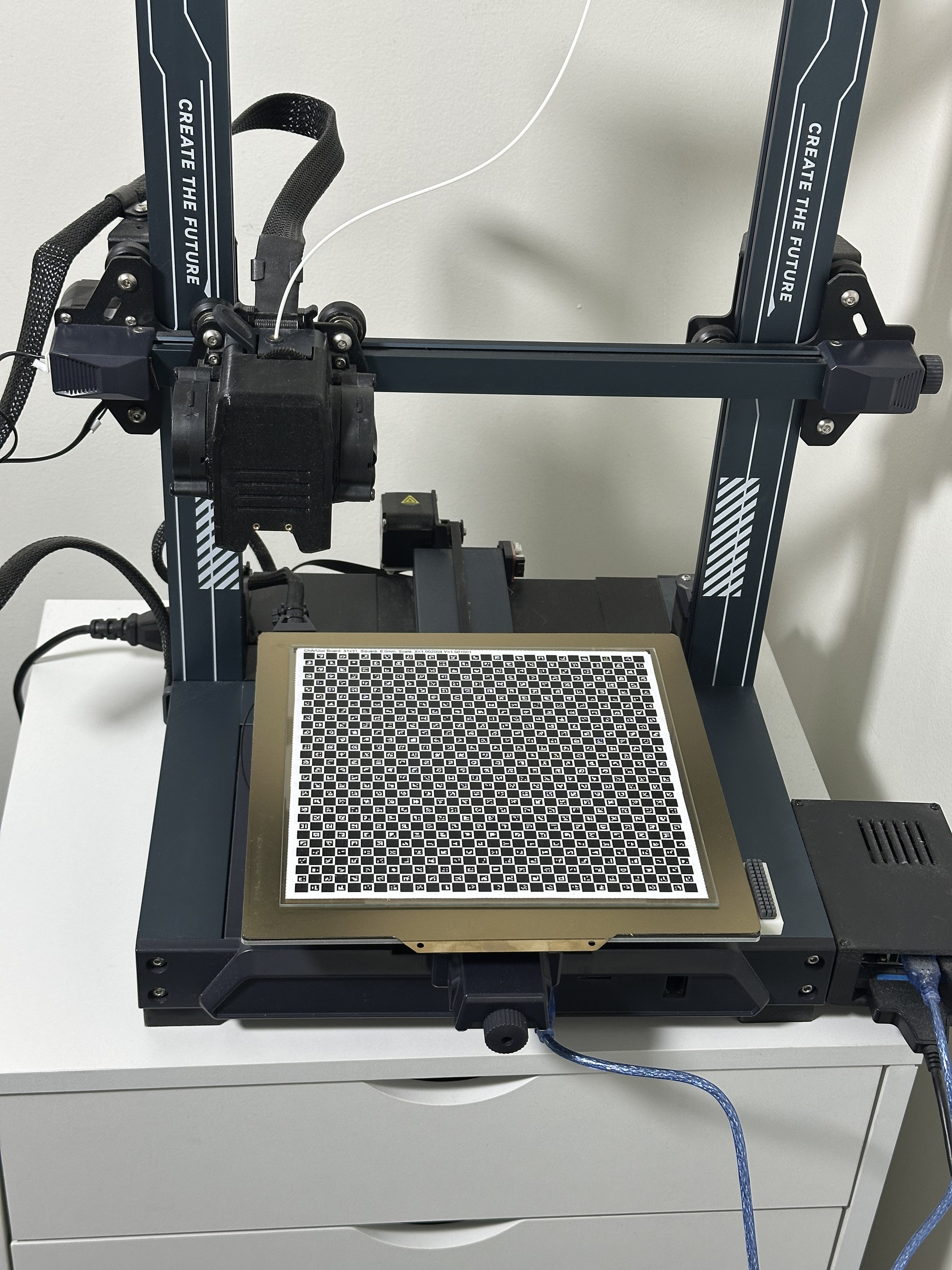
This is a desktop app that measures and corrects skew on Klipper 3D printers using a camera. The usual way to calibrate skew is to print a test square, measure its diagonals with calipers, and type those numbers into Klipper. That wastes filament, and the result is only as good as your caliper measurements. My tool skips all of that. A USB camera on the toolhead scans a printed calibration board on the bed, works out how far the axes are from square, and hands you Klipper commands ready to paste in.
What's Skew?
On a perfect printer, the X and Y axes are exactly 90° apart. In reality
they're usually off by a fraction of a degree, so a square comes out as a
slight parallelogram. You can't see it on small parts, but on big ones the
corners stop lining up and holes drift out of place. Klipper can correct
skew in software with its SET_SKEW command, as long as you
tell it how big the error is. The hard part is measuring it.
Goals
- No test prints: no filament, no calipers
- Fully automatic: the app drives the printer over the network and runs the whole scan by itself
- Measure XY skew, with optional XZ and YZ
- Output Klipper commands that can be pasted straight into the console
How It Works
The idea is simple. The printer moves the camera to a grid of positions over the board. At each one, the camera works out where it actually is relative to the board. If the printer were perfect, the camera's measured positions would line up exactly with where the printer thinks it moved. Skew shows up as a small, consistent mismatch between the two, so you collect a lot of position pairs and fit a transform that explains the difference.
Each scan point goes like this:
- Move the toolhead to the next grid point and wait for it to stop.
- Let the camera settle, then grab a frame.
- Find the board in the image and work out the camera's position relative to it.
- Save the pair: where the printer thinks it is, and where the camera says it is.
Once the scan is done, the app fits a transformation matrix to all the pairs, separates out the skew, and turns it into Klipper commands.
Calibration Board
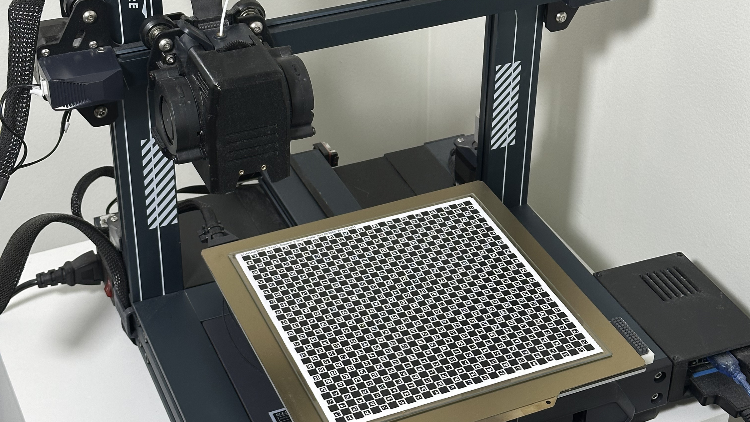
To measure position from an image, the camera needs something to look at with known dimensions. I used a ChArUco board, which is a mix of a regular checkerboard and ArUco markers. Every white square has a small ArUco marker in it: a black-and-white grid that encodes an ID number.
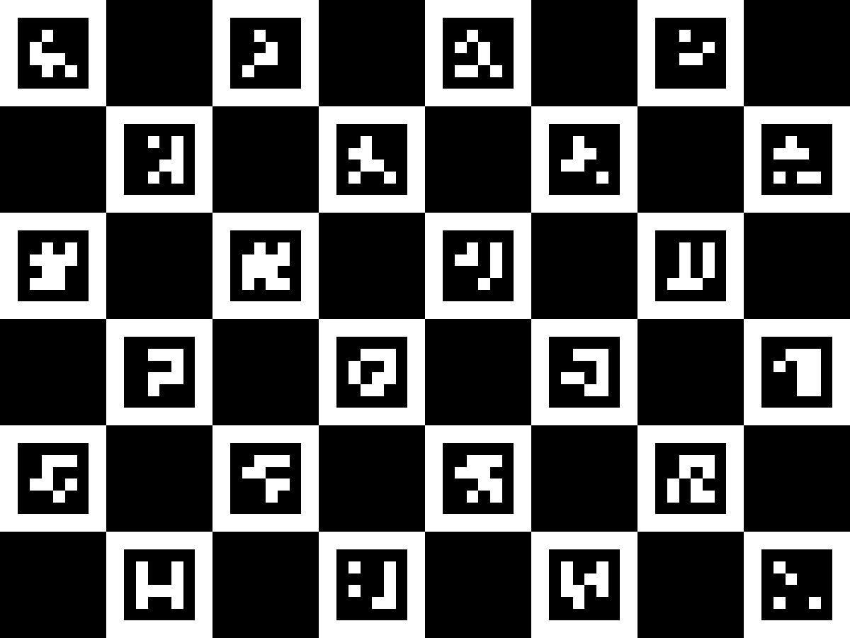
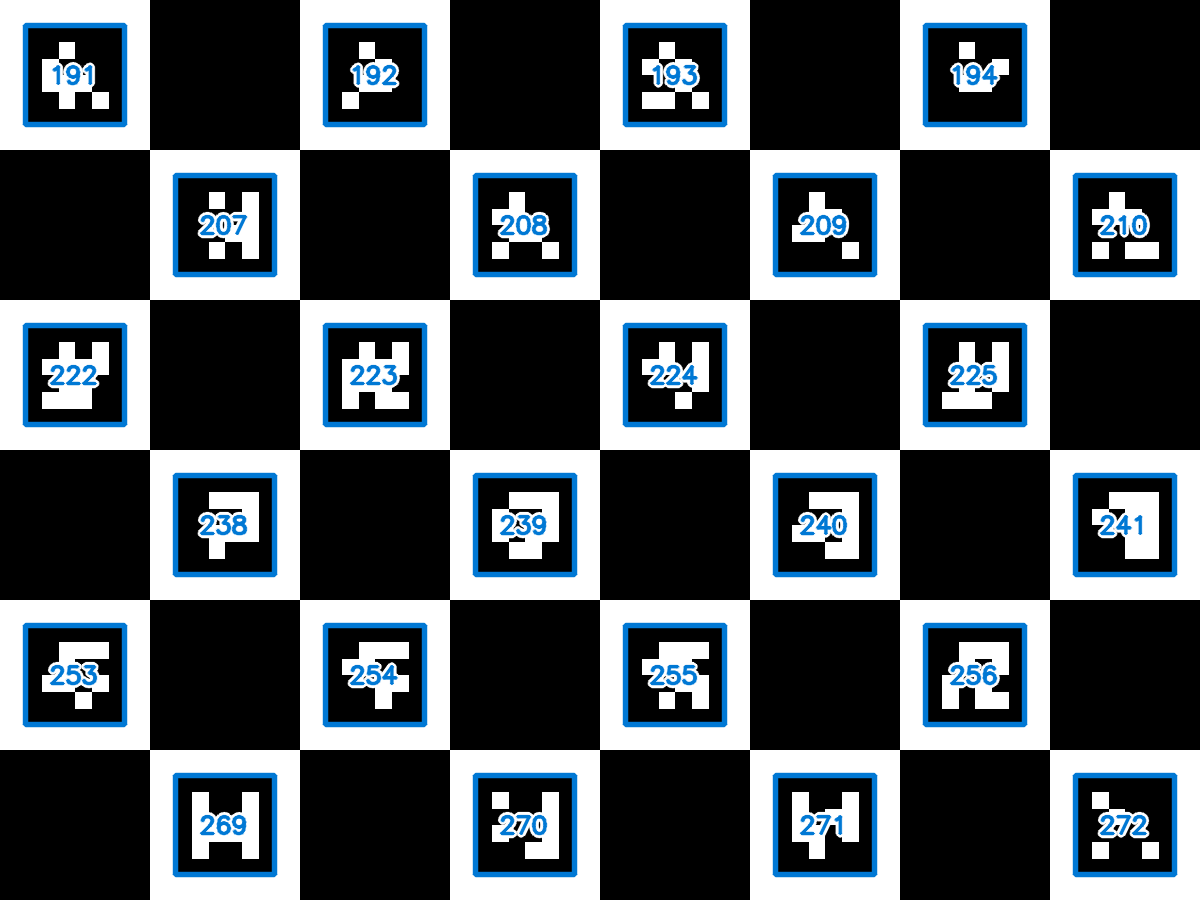
That gives it two big advantages over a plain checkerboard:
- The camera only needs to see part of it. Since every marker has its own ID, the software knows exactly which part of the board it's looking at, even with only a few squares in view. A plain checkerboard needs every corner visible, which is impossible when the camera is close to a board this big.
- Very precise corners. OpenCV first finds the markers to locate the board, then refines the checkerboard corners to a fraction of a pixel. That precision matters when the error you're measuring is a tenth of a degree.
My board is 31 × 31 squares, 6 mm each (186 mm across), with 4 mm markers
from the DICT_4X4_1000 dictionary. I generate it in code with
OpenCV's CharucoBoard class, so the layout always matches what
the detector expects. The board is rendered at 20 px/mm and then put into a
PDF with ReportLab so it prints at its exact physical size.
Board size
There was a catch. The software assumes every square is exactly 6 mm. If the board is even slightly the wrong size, that error ends up in the measurement. It turns out regular paper printers don't print at a perfect 1:1 scale either, and X and Y aren't even off by the same amount.
So I added separate SCALE_X and SCALE_Y
correction factors to the PDF generator, so the board could be stretched by
different amounts in each direction. Finding the right values was a loop:
print, measure with calipers, work out the ratio, update the factors, and
print again. I ended up at SCALE_X = 1.002004 and
SCALE_Y = 1.001001. In other words, my paper printer was
printing about 0.2% short in X and 0.1% short in Y. Across a 186 mm board,
that's about 0.37 mm and 0.19 mm, which is way bigger than the errors I was
trying to measure.
Camera Calibration
Before the camera can measure anything in millimeters, the app needs to know how the camera itself bends light: its focal length, where its optical center is, and how much the lens distorts the image. These are called the intrinsic parameters, and they live in the camera matrix:
\(f_x\) and \(f_y\) are the focal length in pixels, and \(c_x\) and \(c_y\) are the pixel where the optical axis hits the image. A point at \((X, Y, Z)\) in front of the camera shows up at pixel \(u = f_x X/Z + c_x\), \(v = f_y Y/Z + c_y\), before lens distortion bends it a little more.
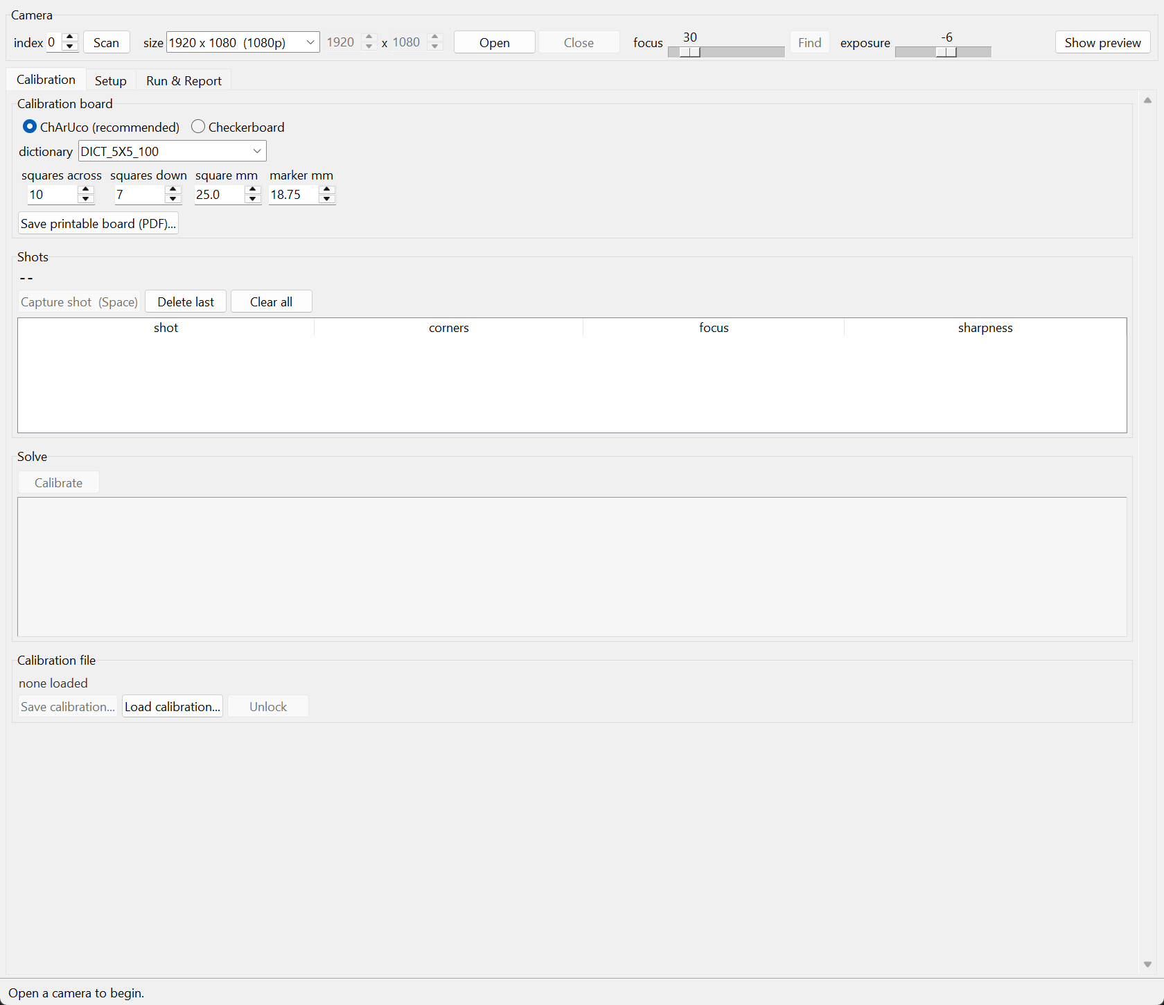
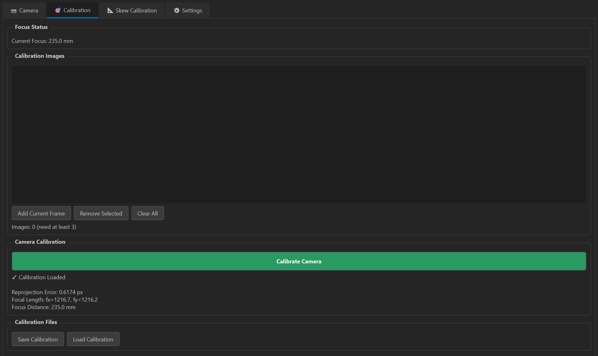
The Calibration tab walks you through measuring these. You take pictures of
the board from a bunch of different angles and distances, and the app runs
OpenCV's calibrateCamera to solve for the camera matrix and
five distortion coefficients. It also reports the reprojection error: how
far, on average, the board's corners land from where the solved model says
they should be. My calibrations came out at 0.50 to 0.62 px on
1920 × 1080 images, with a focal length of about 1,216 px. Calibrations get
saved as JSON, so you only do this once per camera and focus setting.
Position Measurement
With the camera calibrated, each frame gives a position. The app detects
the board, matches every corner it found to that corner's known spot on the
board, and passes those matches to OpenCV's solvePnP. That
solves for the pose of the board relative to the camera: a rotation and a
translation \(t\).
The translation is what gets recorded. The camera is bolted to the toolhead, so it moves with the printer but never rotates. That means every time the toolhead moves, \(t\) moves by the same amount, just seen through a fixed rotation (the camera is never perfectly lined up with the printer's axes) and maybe flipped in direction. Neither of those is a problem, because the fit in the next step soaks both of them up.
In my main test, the camera sat about 71 mm above the board. (The printer was at Z = 80 mm, but Z is the nozzle's height, and the camera is mounted at a different height on the toolhead.) At that height, one pixel covers about 0.06 mm, and the sub-pixel corner refinement gets well below that.
Skew Calculation
At this point there's a list of point pairs: \(m_i\), where the printer thinks the toolhead is, and \(r_i\), where the camera measured it.
Transform fitting
First, both sets of points get centered by subtracting their averages. That removes the offset between the printer's coordinates and the camera's, which doesn't tell us anything about skew. Then the app finds the 3×3 matrix \(A\) that maps camera measurements onto printer positions as closely as possible, using least squares:
\(A\) has everything mixed together: the printer's skew, small scale errors in each axis, and the rotation of the camera relative to the printer. With 42 points and only nine unknowns, the system is heavily overdetermined, which averages out a lot of the noise in individual measurements.
RQ decomposition
To get the skew on its own, the app splits \(A\) with an RQ decomposition:
\(Q\) is orthogonal, a pure rotation (plus any flip). \(R\) is upper triangular, and that's where the scale and skew live:
The order is what makes this work. Reading \(m = R\,(Q\, r)\) from right to left, \(Q\) first rotates the camera's measurements to line up with the printer, and then \(R\) applies the printer's own scale and skew. The camera's rotation belongs to the camera, so it has to come first, which is why it's RQ and not the more common QR.
The diagonal entries are the scale factors for each axis. The off-diagonal entries are the skew: \(k_{xy}\) says how much X moves when Y moves. A perfectly square printer would have \(k_{xy} = 0\). Dividing each row by its diagonal and taking the arctangent gives the skew angles:
Before that, the app flips the sign of any row whose diagonal came out negative, so a flipped camera axis doesn't show up as a negative scale.
Klipper commands
Klipper's SET_SKEW command doesn't take an angle. It takes the
three measurements from the old test-square method: the two diagonals and
one side (AC, BD, and AD). So the
app goes backwards. It works out what a 100 mm test square would have
measured on a printer with this much skew, and gives Klipper those numbers.
Klipper then gets the same input it would have gotten from calipers, minus
the calipers.
One subtlety: the fitted matrix maps the camera's measurements onto the printer, so it describes the correction, not the skew itself. A printer leaning +0.1° gives a matrix leaning −0.1°. The app flips the sign before generating the command, because Klipper wants the physical skew and works out its own correction.
The output looks like this, ready to copy with one button:
SET_SKEW XY=<AC>,<BD>,<AD>
SKEW_PROFILE SAVE=cv_calibration
SAVE_CONFIG

# In your START_PRINT macro:
SKEW_PROFILE LOAD=cv_calibration

# In your END_PRINT macro:
SET_SKEW CLEAR=1
Scanning
The app talks to the printer over the network through the Moonraker API. It homes the printer, then generates a grid of scan points from your settings: grid spacing, margin from the edge, and scan height.
A few details took some thought:
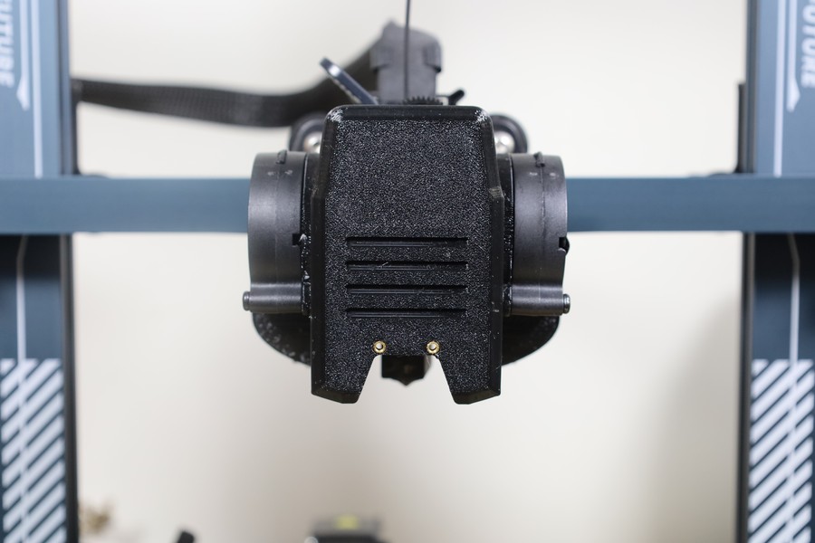
- Camera offset. The camera isn't where the nozzle is. Mine is offset 50 mm in Y. The grid is laid out for where the camera should be, and the app subtracts the offset to work out where to send the nozzle, skipping any point that would put the nozzle off the bed.
- Board-only mode. If the board doesn't cover the whole bed, the grid can be limited to just the board area, so every point has something to look at.
- Short travel. The points are put in nearest-neighbor order: start at the origin, and always go to the closest point that hasn't been visited yet. It's not a perfect shortest path, but it's simple and cuts out most of the back-and-forth.
- Waiting for it to stop. Every move ends with
M400, which makes Klipper wait until the move has actually finished. Then the app waits another settling delay (500 ms on my setup) so the toolhead stops wobbling before it takes the picture. - Z safety. Every move is clamped to a minimum Z height, so a bad setting can't drive the camera into the board.
- Resume. If a scan gets interrupted, like by a network timeout, it can pick up from the last good point instead of starting over. Points where the board isn't detected are skipped instead of stopping the scan.
The App
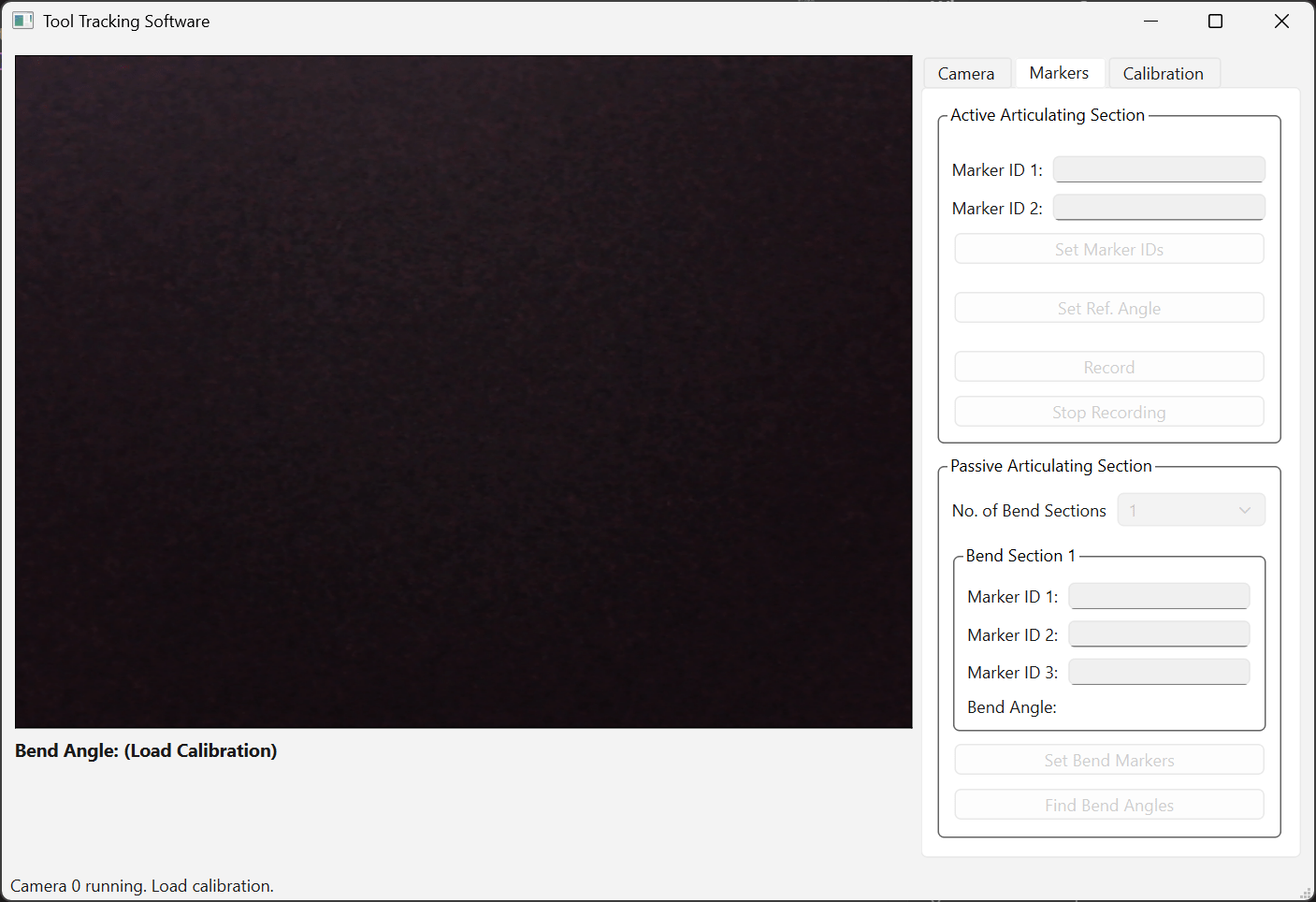
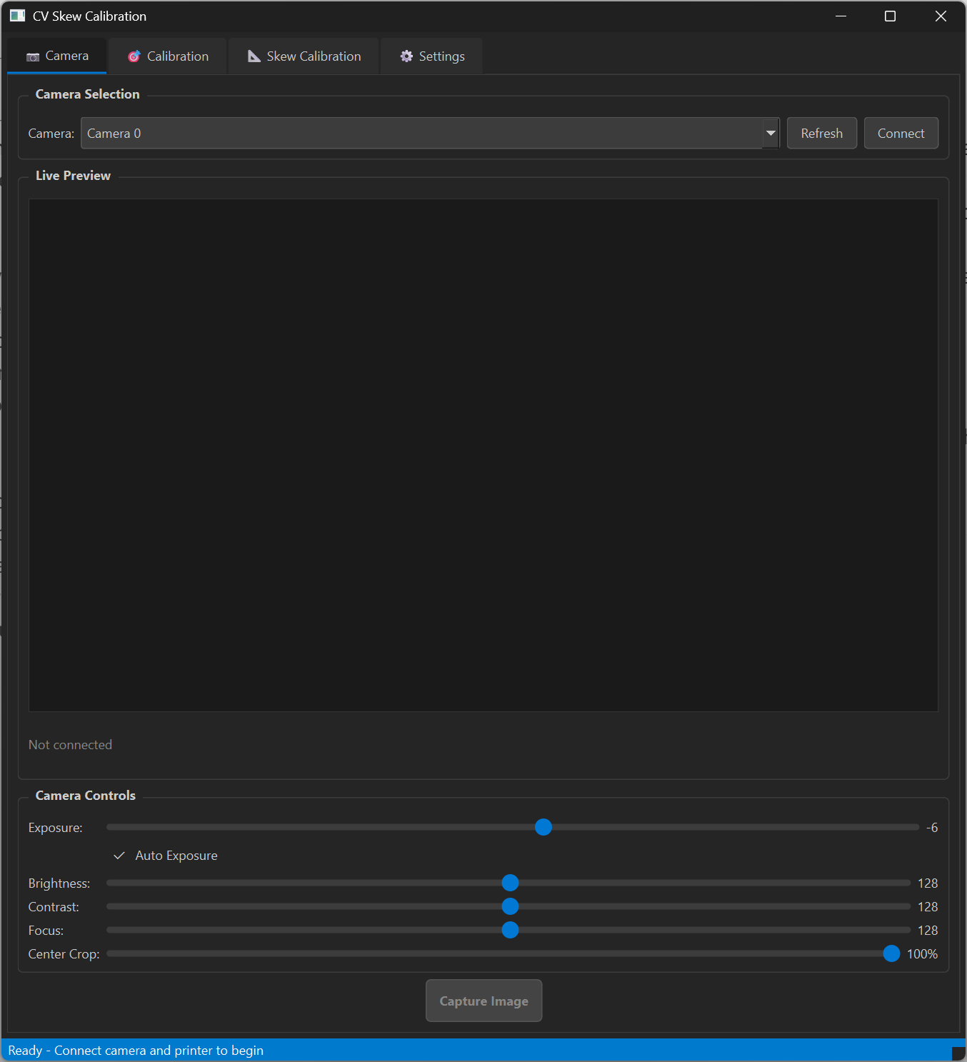
The interface is a dark-themed PyQt6 app with four tabs:
- Camera: live video with manual exposure, brightness, contrast, and focus. A center-crop slider lets you ignore the edges of the frame, where lens distortion is worst and detections are least reliable.
- Calibration: the camera calibration workflow from above.
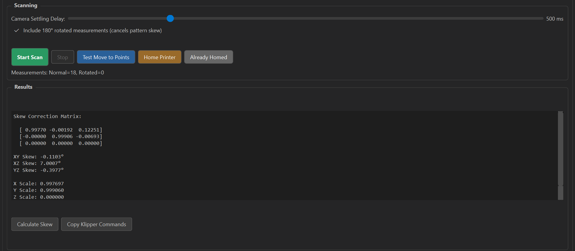
- Skew: scan setup, printer connection, homing, the scan itself, and the results with the Klipper commands.
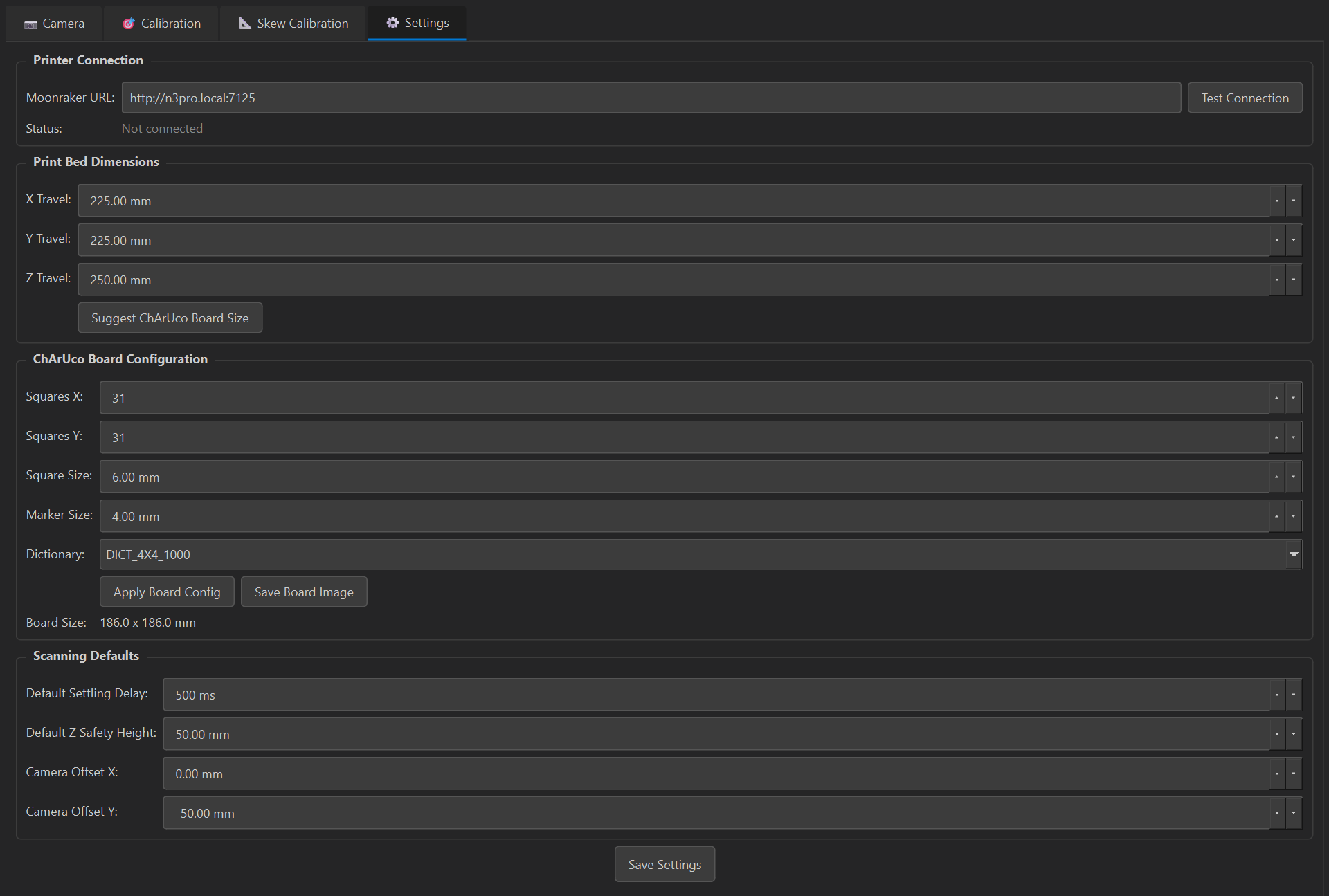
- Settings: the Moonraker URL, bed size, board parameters, camera offsets, settling delay, and Z safety height. Everything is saved to a
config.jsonfile.
Testing
For my main test, the camera scanned a 7 × 6 grid at 25 mm spacing, which is 42 points, with the toolhead at Z = 80 mm. The scan found a little over 0.1° of XY skew.
I applied the correction in Klipper, and it fixed the skew reasonably well.
Conclusion
A camera and a printed board turned out to be enough to measure skew without printing a single test part. The scan found a little over 0.1° of XY skew, and the correction the app generated fixed the skew reasonably well.
Thanks for reading!